Showing posts with label UPS. Show all posts

Thursday, January 3, 2019

Battery Systems for Mission Critical Infrastructure - Design, Maintenance and Testing (1)


Proper design, maintenance, and testing of battery system in mission critical facilities are crucial for business continuity and safety.

In these articles, we are going to

(1) Understand the need for reliable batteries in mission critical facilities;
(2) Explore the most common battery abnormalities that can be spotted through inspection; and
(3) Review simple steps that can be taken to find out battery problems.

When we say the systems are mission critical, it means "Power remains uninterrupted!". But this mission critical label does not apply to every single part of the facility. Some processes are more important to the business than others, and that is where the focus of the design lies. Certainly, designing for a mission critical facility can be challenging. There are many considerations in play. The system has to be very robust with no single point of failure.

Designing electrical systems, maintenance is an important factor, especially in deciding what battery to implement. Maintenance includes but not limits to the cost of replacement of a battery cell. It also involves the accessibility of the battery system, the ease of disassembly and reinstallation, the frequency of service, and the conditions needed in the actual environment (temperature, humidity, etc.).


The goal of maintenance is to prolong the life of batteries and to make sure the batteries perform as designed. Inspection is done to catch any abnormalities that could impact battery performance as well as long-term life expectancy. It is important to place the batteries in an environment that agrees with the manufacturer’s recommendations.


Battery Types


There are several types of batteries used for providing power to electrical systems. The most popular types of batteries being used nowadays are lead-acid and nickel-cadmium (NiCd). NFPA 110: Standard for Emergency and Standby Power Systems defines two types of lead-acid batteries:

Valve-regulated lead-acid (VRLA): A lead-acid battery consisting of sealed cells furnished with a valve that opens to vent the battery whenever the internal pressure of the battery exceeds the ambient pressure by a set amount.

A typical valve-regulated lead-acid (VRLA) battery used in an uninterruptible power supply (UPS) application


Vented (or flooded): A lead-acid battery consisting of cells that have electrodes immersed in liquid electrolyte. Flooded lead-acid batteries may have a provision for the user to add water to the cell and are equipped with a flame-arresting vent, which permits the escape of hydrogen and oxygen gas from the cell in a diffused manner such that a spark, or another ignition source, outside the cell will not ignite the gases inside the cell.

Although NFPA 110-2010 recognizes the usage of NiCd batteries for emergency systems, no definition is provided for such batteries. A definition can be found in IEEE 1106-2015: Recommended Practice for Installation, Maintenance, Testing, and Replacement of Vented Nickel-Cadmium Batteries for Stationary Applications (https://standards.ieee.org/findstds/standard/1106-2015.html).


Battery Uses


Mission critical facilities are not only the buildings that are critical to human life, such as hospitals, but also are facilities for business continuity, like data center. Many methods are employed to mitigate the risk of power outages. But, almost always, the risk mitigation relies upon batteries. Uses include:

Uninterruptible Power Supply (UPS) Systems: Batteries are used to back up power where UPSs are involved. While the power is processed and converted through the UPS to the load, the batteries are kept charged to provide the much-needed power to the critical system when normal power is out. Even though standby generators are most likely used as backup power, the batteries provide the critical power needed until the generators are able to receive load.


Standby Generators: Batteries are used to provide the initial crank to the generators as well as power the generator controls.

Controls: Batteries also are used to back up controls, especially when medium-voltage distribution is found throughout the facility. Nowadays, the operation of critical systems is more reliant on controls to avoid nuisance tripping and to enable fast-acting protection.


Emergency Systems: Batteries are widely used to back up life safety systems, such as exit lights. Exit lights normally are backed up by a 90-minute battery to allow people to recognize the way out of the building in case of a life-endangering situation. All of the above-mentioned uses (UPS, generators, and controls) could be part of an emergency system as well.


Next Article:
Battery Systems for Mission Critical Infrastructure - Design, Maintenance and Testing (2)


About us


SMA connects IT, Facilities and Design. For the other design considerations, please visit 

(1) Site Selection,
(2) Space Planning,
(3) Cooling,
(4) Redundancy,
(5) Fire Suppression,
(6) Meet Me Rooms,
(7) UPS Selection,
(8) Raised Floor,
(9) Code & Standards,
(10) Transformers and Harmonic Distortion,
(11) Multi-mode UPS Systems,
(12) Electrical Rooms,
(13) Generator Systems,
(14) Generator Fuel Systems, 

(15) Battery Systems, etc.

All topics focus on key components and provide technical advice and recommendations for designing a data center and critical facilities.


Strategic Media Asia (SMA) is one of the approved CPD course providers of the Chartered Institution of Building Services Engineers (CIBSE) UK. The team exists to provide an interactive environment and opportunities for members of ICT industry and facilities' engineers to exchange professional views and experience.


Friday, January 12, 2018

Electrical System Design - Grounded or Ungrounded?

Further to the discussion of Earthing & Grounding for UPS System, we are going to explore different cases making mistakes to ground everything by default which creates parallel paths and are strictly prohibited!


We all note that ungrounded electrical systems are not often employed due to real and perceived safety concerns. Predominately, commercial systems are solidly grounded (SG). SG systems are characterized by high line-to-ground fault current with reliance on quick overcurrent protection to limit the release of dangerous energy.

Alternatives to an SG system include low-resistance grounding (LRG), reactance grounding (RG), and high-resistance grounding (HRG). LRG or RG systems are recommended on medium-voltage systems to limit fault currents while overcurrent protection operates. HRG systems, which limit the fault current to a small value, were adopted by the mission critical data centers. Onsite power generation and uninterruptible power supply (UPS) systems are used extensively where equipment costs can be justified against the losses due to business continuity interruptions:-


The picture shows an UPS installed in a typical equipment room with associated switchgear. This is a good illustration where the user is planning for future growth of the UPS, and has allowed space for additional modules to add capacity or redundancy.


Transformerless UPS systems are preferred due to efficiency savings, lower thermal heat rejection, and a smaller footprint as compared with transformer-based UPS systems. These transformerless systems have been introduced in the past decade and are commonly employed on a large scale for data centers and critical manufacturing processes. For domestic, medium- to large-scale applications, engineers are specifying UPS distribution as a 480 V, 3-wire system with 208 V power distribution units (PDUs) at the point of connection. A PDU or isolation transformer is provided when single-phase loads are served. A neutral is not required or advised for this system until single-phase loads are required:-


This 3-wire UPS system depicts an ungrounded zone. Ungrounded operation occurs during battery discharge when the UPS isolates the incoming source.


For smaller systems, such as a 208/120 V UPS input source, a 4-wire system may be specified (see the following figure). Systems in both figures operate ungrounded during an event where power is lost. Whether a short circuit is flowing through the neutral or grounding conductor when the UPS is providing power, transistors in the UPS rectifier isolate the input power, opening the supply circuit and interrupting the return path:-


This 4-wire UPS system depicts an ungrounded zone. Ungrounded operation occurs during battery discharge when the UPS isolates the incoming source.


For applications that can’t tolerate an ungrounded zone within the electrical distribution system, an isolation transformer inside the UPS is an option. Without an isolation transformer, there is no safe way to connect the direct-current source to ground without introducing a parallel return path. With transformerless applications being the leading choice in the industry, it is important for engineers to mitigate and understand the risks of operating an ungrounded system during power transfer.

Careful application of grounding continues to rank No. 1 in safety priority. It is a mistake to ground everything by default. Grounding duplication creates parallel paths, which is strictly prohibited for neutral conductors.

By design, when connecting exposed metal cabinets and conduit to the grounding system, there are many parallel paths to the source. However, properly grounded systems are only connected once at the source. A grounded conductor is provided to intentionally return unbalanced current back to the source. These grounded conductors are separated from the grounding system to avoid a parallel return path. Most important, the isolation of a grounded conductor from grounding keeps these intended and unintended exposed metal paths from carrying current under normal conditions.

For critical applications, redundant components along with alternative utility and standby sources are normal practices. These separately derived systems are grounded at the source and interconnected by transfer-switch schemes. Grounding interconnection is required and care must be taken to avoid hazards, such as not being able to isolate a ground fault or circulating ground currents. Where 4-wire sources are required, auto-transfer schemes must consider switching the neutral.


About us

Strategic Media Asia (SMA) is one of the approved CPD course providers of the Chartered Institution of Building Services Engineers (CIBSE) UK. The team exists to provide an interactive environment and opportunities for members of ICT industry and facilities' engineers to exchange professional views and experience.

SMA connects IT, Facilities and Design. For the Data Center Design Consideration, please visit 

All topics focus on key components and provide technical advice and recommendations for designing a data center and critical facilities.


Tuesday, December 5, 2017

Boost Your Data Center Efficiency with Multi-mode UPS Systems

When consulting-specifying engineers look at the hundreds of technology factors that go into a data center’s design, they know that even small variables, when multiplied by big numbers, add up quickly. That’s the case with seemingly small incremental increases in energy efficiency for uninterruptible power supply (UPS) systems used in data centers around the world.

According to the Uptime Institute, traditional transformer-based UPS devices represent only 12% of a typical data center’s energy consumption, given power use and energy conversion inefficiencies and heat loss. Although they account for only a fraction of the total energy consumption in a data center, even small improvements in UPS energy conversion efficiency can add up to significant lifecycle operational cost savings.


Figure 1: Typical Data Center AC-Power Configuration


Traditional double conversion UPS units (Figure 1), which protect the load during outages — use a rectifier to convert the alternating current (ac) power to direct current (dc) power, and an inverter to provide safe and clean ac power to the load using either the main or battery power.

Unfortunately, in this scenario power efficiency is the price paid for protection. Transformer-based double conversion UPS systems have a typical power efficiency rating in the range of 88% to 92%. As a result, double conversion UPS systems place a steep toll on annual data center energy operating budgets.

Newer three-level insulated gate bipolar transistor (IGBT) UPS technologies, which reduce switching and filtering power conversion losses, offer efficiency levels approaching 97% in double conversion mode, and up to 99% efficiency when operating in energy-saving multi-mode. These new, three-level UPS topologies create new OpEx rationales when designing data center power systems and specifying UPS technologies.


Multi-mode Transfer Speed


So what’s that optimum switching or transfer time? According to a Green Grid white paper on multi-mode (or eco-mode), “if, for example, a UPS has a transfer time of greater than 10 ms and is paired with information technology (IT) equipment that has ride-through capabilities of only 10 ms, the UPS may not be able to support the IT equipment.”

That’s one of the reasons a few companies design their multi-mode UPS products with transfer speeds of less than 2 ms. The technologies that help achieve these speeds are seamless and represent a robust set of power disturbance detection, analysis, and control systems.

When a multi-mode UPS unit’s responsive monitoring technologies detect any sort of deviation on the main or bypass power path, the inverter is immediately turned on to allow quality power to flow from the double conversion premium protection mode. In the same instant, the static switch on the bypass path from the utility is turned off to block the disturbance from reaching the load.

A variety of disturbance analyzers and fast-switching technologies are employed in combination, including


  • An instantaneous adaptive voltage error detector that monitors subtle changes in amplitude and duration
  • A root mean square (RMS) voltage error detector that computes the RMS of all three UPS output voltages for variances
  • An output short circuit detector that, after a breaker is tripped, will automatically increase line current to rapidly clear and reset the breaker
  • A sophisticated transient inverter controller that quickly manages the transfer of the load to inverter power and back again to the bypass path.


All of these advanced monitoring and control systems work in concert to anticipate and respond to a comprehensive set of possible power conditions, creating a transfer switch speed of less than 2 ms. This speed helps to maximize the intermittent transfer to double conversion protection, while maintaining higher multi-mode efficiency for the majority of the time when quality utility power is flowing.


Lifecycle Costs


In evaluating efficiency and lifecycle costs for multi-mode UPS systems, some might ask: If our UPS running in double conversion already gets us to 93% efficiency, why take a “risk” for a few percentage points in efficiency? Can that extra energy efficiency provide a significant return?


Figure 2: Small percentage improvements in power efficiency can yield significant savings over a 10-year period.


If we look at a UPS deployment at a typical 10 MW data center realizing just a 1% gain in efficiency, we can see a significant impact over 10 years. As Figure 2 shows, while CapEx (Capital Expenditure) are fixed, a Total Cost of Ownership (TCO) evaluation of the OpEx (Operating Expense) for running an UPS over 10 years creates an operational savings of $1.4 million when energy efficiency improves a single percent — from 93% to 94% efficiency. With newer multi-mode UPS technologies that provide up to 96.5% efficiency, that savings could jump to almost an additional $3.4 million.

As both corporate and data center providers challenge their consulting-specifying partners to deliver projects that balance capital and lifecycle costs, as well as ensure the reliability and energy efficiency of their facilities, new multi-mode UPS efficiency models provide a compelling set of tools for data center designers and engineers.


About us

Strategic Media Asia (SMA) is one of the approved CPD course providers of the Chartered Institution of Building Services Engineers (CIBSE) UK. The team exists to provide an interactive environment and opportunities for members of ICT industry and facilities' engineers to exchange professional views and experience.

SMA connects IT, Facilities and Design. For the Data Center Design Consideration, please visit 

All topics focus on key components and provide technical advice and recommendations for designing a data center and critical facilities.


Tuesday, August 1, 2017

Data Center Design Consideration: Transformers and Harmonic Distortion


Data center managers and information technology (IT) engineers in today's critical facilities are in search of reliable and energy-efficient equipment with low total cost of ownership. But after equipment investments are made, it's important to pay attention to possible threats to the operational efficiency.


One threat that is often overlooked is harmonic currents, which can have a significant impact on electrical distribution systems and the facilities they feed. Wasted power and temperature fluctuations caused by these currents can prevent facilities from achieving maximum efficiency, so it's more important than ever for data center managers to evaluate their facilities and to take the time to develop a strategy mitigating harmonic current.


Harmonic Distortion


Harmonics are distortions of the normal electrical current waveform, generally transmitted by nonlinear loads. Switch-mode power supplies (SMPS), variable speed motors and drives, photocopiers, personal computers, laser printers, fax machines, battery chargers, and UPSs are examples of nonlinear loads. Single-phase nonlinear loads are prevalent in modern office buildings, while 3-phase nonlinear loads are common in factories and industrial plants.

A large portion of the nonlinear electrical loads in most electrical distribution systems comes from SMPS equipment. For example, all computer systems use SMPS that convert utility ac voltage to regulated low-voltage dc for internal electronics. These nonlinear power supplies draw current in high-amplitude short pulses that create significant distortion in the electrical current and voltage wave shape (Figure 1). This harmonic distortion, measured as total harmonic distortion (THD), travels back into the power source and can affect other equipment connected to the same source.


All periodic waves can be generated with sine waves of various frequencies. The Fourier theorem breaks down a periodic wave into its component frequencies.

Harmonic currents generated by nonlinear loads increase power-system heat losses and power bills for end users. These harmonic-related losses reduce system efficiency, cause apparatus overheating, and increase power and air conditioning costs. As the number of harmonics-producing loads has increased over the years, it has become increasingly necessary to address harmonics when making any additions or changes to a facility. 

Most power systems can accommodate a certain level of harmonic currents but will experience problems when harmonics become a significant percentage of the overall load. As these higher frequency harmonic currents flow through the power system, they can cause communication errors, overheating, and hardware damage. 


Reducing Harmonics


To determine if harmonic mitigation is necessary, facilities managers should conduct an assessment to precisely measure the harmonics affecting the data center and identify their origin. Solutions for harmonic mitigation vary in complexity and cost and can be deployed individually or in combination. The strategy that makes the most sense for a facility will vary based on the loads it supports, its budget, and the nature of the harmonic-related problems it is experiencing.


Solution 1 - K-rated Transformers in Power Distribution Components


A standard transformer is not designed for high harmonic currents produced by nonlinear loads. It will overheat and fail prematurely when connected to these loads. Therefore, when harmonics were first introduced into electrical systems at levels that showed detrimental effects (circa 1980), the industry responded by developing the K-rated transformer. K-rated transformers are not used to eliminate harmonics, but to manage the heat generated by harmonic currents.


K factor ratings range between 1 and 50. A standard transformer designed for linear loads is designated with a K-factor of 1. The higher the K-factor, the more heat from harmonic currents the transformer is able to withstand. When selecting a K rating, managers should consider the trade-offs between size, efficiency, and heat tolerance. For example, transformers with higher K factors are typically larger than those with lower K factors. The table shows appropriate K ratings to use for different percentages of nonlinear current in the electrical system.


Power distribution units (PDUs) with a K 13-rated transformer are readily available to efficiently handle harmonic currents. Units with K 20 transformers are common, but are typically overkill for most modern data centers.


Units with K 20 transformers are common, but are typically overkill for most modern data centers. The K-rated, dry-type transformer is widely used in electrical environments - either in a PDU or as a stand-alone unit. However, recent advances in transformer design are changing the way facilities managers reduce voltage distortion and power loss caused by harmonic currents. 


Solution 2 - Harmonic Mitigating Transformer


A harmonic-mitigating transformer (HMT) is designed to handle the nonlinear loads of today's electrical infrastructures. This transformer uses electromagnetic mitigation to deal specifically with the triplen (3rd, 9th, 15th, and so on) harmonics. Secondary windings of the transformer are arranged to cancel zero sequence fluxes and eliminate primary winding circulating currents. This transformer also addresses the 5th and 7th harmonics by using phase shifting.


Using these two electromagnetic techniques, an HMT allows loads to operate as they were intended, while minimizing the energy loss and distortion caused by harmonics. Most HMTs exceed NEMA TP-1 efficiency standards, even when tested with 100% nonlinear loads. Wherever a K-rated transformer is specified, an equivalent HMT is a direct substitute.


Solution 3 - Harmonic Mitigating UPS


Much like an active filter, harmonic-mitigating UPS eliminates harmonic distortion by inserting equal and opposite current into the line. They also compensate for reactive power from low power-factor loads and balance loads across 3-phase systems to avoid stranded capacity, as well as to provide clean and continuous power during utility outages or in response to electrical disturbances.


Going Further


Data center managers are increasingly deploying UPSs with energy-saver operating modes to boost efficiency and lower power costs. Recently, harmonic-mitigating UPSs capable of keeping distortion within predetermined and adjustable limits, correcting power factor, and balancing loads while in energy-saver mode have begun to reach the market.

These new systems typically remain within 1% of energy-saver levels while performing these functions, a significant improvement over past technologies. The harmonic mitigation technology in the latest energy-saver UPSs is a built-in feature that requires no additional footprint, saving valuable data center floor space and reducing installation and maintenance costs.

Harmonics continue to be costly for data centers, preventing data center managers and engineers from achieving maximum reliability and efficiency. Fortunately, the latest enhancements in UPS technology offer next-generation harmonic-mitigation capabilities. Though not always required, such systems enable data centers to achieve the highest efficiency possible by actively correcting for harmonic currents as they occur.


About us


Strategic Media Asia (SMA) is one of the approved CPD course providers of the Chartered Institution of Building Services Engineers (CIBSE) UK. The team exists to provide an interactive environment and opportunities for members of ICT industry and facilities' engineers to exchange professional views and experience.

SMA connects IT, Facilities and Design. For the Data Center Design Consideration, please visit 


(1) Site Selection,
(2) Space Planning,
(3) Cooling,
(4) Redundancy,
(5) Fire Suppression,
(6) Meet Me Rooms,
(7) UPS Selection, and
(8) Raised Floor

All topics focus on key components and provide technical advice and recommendations for designing a data center and critical facilities.


Wednesday, April 5, 2017

A Data Center Nightmare: Single Point of Failure (2)

Refer to "A Data Center Nightmare: Single Point of Failure (1)"


Data center failures can be rooted in several sources - design, construction, maintenance, quality of material, quality of equipment, commissioning and direct human intervention. For the most part, data centers, even ones that fail, have the benefits of good design practice and intention, professional construction oversight, and high-quality craftsmanship. They are maintained according to data center quality guidelines. But a single overlooked mistake can quickly become significant issues - power and air conditioning failure - that can bring down a data center.

Another story is a high-profile government data center, with a busduct-panelboard connection exploded, effectively shutting off power to approximately 15,000 square feet of the most critical computing in the facility.


In this incident, the design relied on an isolated redundant uninterruptible power supply (UPS) back-up. When a UPS system failed, a static automatic transfer switch was to shift to the already-operating isolated redundant UPS and transfer the load within a quarter cycle. The system worked well and the client was satisfied with the transfer scheme and the rotary concept.


Source of the Problem


Where this system failed was downstream from the automatic transfer switch. Each of the switches fed one busduct riser and terminated directly into a main distribution panel located on each floor of the facility - one busduct per panel. A single fault on any busduct or main distribution panel compromised the critical load.

As it occurred, the electrical connection between the busduct and the distribution panelboard failed and the load was lost. A single point of failure succeeded in bringing down the floor. Not until the facility’s electricians ran jumper cables from one of the intact risers and back-fed the main distribution panel did the floor have power.


Why did this failure occur? The building had been designed in tight coordination between the government representative and the designer; the entire system had been commissioned and had been running with tight oversight for more than two years. What happened?

The cause of the problem was the failure of a manufactured busduct connector, one of hundreds in the building. The connector joined lengths of feeder busduct via a sliding piece - designed to slide approximately one-quarter of an inch to make installation easier - and a break-away torque bolt designed to ensure that the installer did not over-torque the bolt.

Although the investigation team was not asked to explain exactly why the joint exploded, it determined that the quarter-inch of play designed into the connector had actually allowed for a portion of uninsulated section of the copper busduct to be exposed to the atmosphere without insulation. The team surmised that the perfect combination of air borne dust, humidity and possibly other contaminants led to an arc that became a fault and exploded.

During the analysis, the investigation team isolated each busduct riser from the static automatic transfer switch at the source and from the main distribution panel at the termination. During the megger test, the electrical forensic team discovered two additional joints that didn’t pass, clearly more candidates for potential failure. Not only did the joints not pass the megger test, two of them visibly and audibly arced while the voltage was ramped up during the testing. The joints had shown themselves to be the weak link in the system. The installed busduct technology was vulnerable to catastrophic failure.


Continue - A Data Center Nightmare: Single Point of Failure (3)


About the Blog


Strategic Media Asia (SMA) is one of the approved CPD course providers of the Chartered Institution of Building Services Engineers (CIBSE) UK. The team exists to provide an interactive environment and opportunities for members of ICT industry and facilities' engineers to exchange professional views and experience.

SMA connects IT, Facilities and Design. For Data Center Design Consideration, please visit 


(1) Site Selection,
(2) Space Planning,
(3) Cooling,
(4) Redundancy,
(5) Fire Suppression,
(6) Meet Me Rooms,
(7) UPS Selection, and
(8) Raised Floor

All topics focus on key components and provide technical advice and recommendations for designing a data center and critical facilities.


Friday, September 30, 2016

Earthing & Grounding for UPS Systems

Power requirements for data centers and other mission-critical facilities continue to grow. While specific requirements of a facility's power distribution depend on the nature of its critical activities — and its anticipated future growth — most rely on large-scale uninterruptible power supply (UPS) systems. These systems, in turn, depend on effective grounding.


The Nature of Power

Before addressing the issue of effective grounding of UPS systems, it is worthwhile, first, to consider the levels of power reliability that characterize electrical systems for one type of mission-critical facility: the data center.


The Uptime Institute provides a tier system of classifications and certification for reliability of mechanical and electrical systems in data centers. There are four tiers: I, II, III and IV. Most data centers have relatively similar components, typically designed to meet Tier-IV requirements — but constructed for Tier-III capacity.

Tier IV design, according to the Uptime Institute, is 2N electrical distribution , which means that power is distributed to critical loads via two different — and redundant — paths. Loss of one feeder anywhere in the distribution will not disrupt power to the critical load. To meet the Tier-IV design, equipment must be rated for dual-cord, dual-input configuration. Power is available on both cords, but only one is utilized. Upon loss of power to one cord, the load transfers to the second cord seamlessly.


Most data centers, however, are not constructed to Tier-IV specifications, which can be extremely cost-prohibitive. Instead, data centers and mission-critical facilities are designed and constructed to Tier-III specifications. Tier III employs N+1 redundancy in the service, UPS modules, mechanical systems and concurrent maintenance systems. A simplified Tier-III single line is illustrated below.


Single or dual medium-voltage power is brought to the facility and transformed to low voltage for distribution. Generators are installed to provide 100% backup so that prolonged loss of utility power will have no impact on data-center operation. Transfer between the utility power and generators can be at low or medium voltage.

Loads are segregated into three categories of power: HVAC, critical and house. Each category may have multiple double-ended substations, depending on the load requirements. The HVAC substations provide power to all mechanical equipment associated with cooling the facility. The house-power double-ended substation provides power to all non-critical spaces, such as administration, support spaces and lighting. The critical-power double-ended substation that is protected by a UPS provides conditioned power to the critical components of the data centers — the servers, direct-access storage drives and disk storage.

Most power supplied to a data center is conditioned power with stored energy as reserve. Consequently, the UPS requirements are very large in magnitude, ranging into the megawatts. This creates a distribution nightmare, considering that most readily-available single-module UPS are at most rated at 800 kilovolt-amperes (kVA). To develop high capacity output of UPS power, single-module UPS systems are installed in parallel. As many as seven modules may be installed in parallel to increase the capacity of the UPS systems.


Static-Switch Bypass

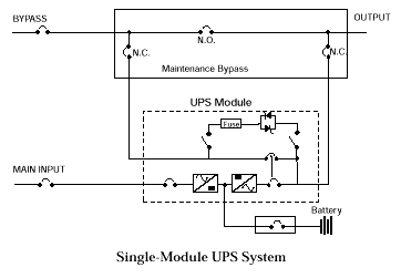
A large UPS system is typically provided with a static-switch bypass . If the UPS modules fail, the critical load will transfer to this bypass. Some designers also provide a wraparound maintenance bypass to the static switch, so as to isolate the UPS modules and static-switch bypass. However, the maintenance bypass provides unconditioned power to the critical load—with no stored energy reserve as backup.


In the event of a power loss—even for just milliseconds—the batteries associated with UPS modules provide the power to maintain continuity. If there is loss of power to the UPS module, the batteries will continue to provide power until their capacity is depleted and a low-voltage condition occurs. At that time the static bypass will transfer to a secondary source, if available and within voltage tolerances.


The Importance of Grounding

Tier-III installations are typically designed with N+1 modules — the total number of modules necessary to meet the load requirements, plus one additional module for redundancy — and are provided with a static-switch bypass to transfer power in the event of failure of the UPS modules. It is important that, if there is a problem with the UPS modules, the critical load transfers from UPS modules to static-switch bypass. In order for the transfer to occur, a good solid ground must be established.

Typically a ground wire is run, along with phase conductors, from the service substation to static-switch bypass. If the termination is not installed or maintained properly, an impedance may develop between the two reference grounds and cause increased voltage in the circuit phase conductors, pushing the tolerance range within which the bypass will transfer and causing the static switch to fail to transfer, even though a good secondary source is available.

It is vital that the ground is properly connected at the static-bypass cabinet, and zero potential is maintained at the neutral to ground bond at the static bypass and at the double-ended substation. Otherwise, the UPS system could fail to transfer to static bypass.

Most manufacturers recommend that a neutral and ground conductor be run from output isolation transformers from the UPS modules to static-switch bypass, where they will be connected to their respective bus. The neutral and ground should be bonded — in accordance with National Electrical Code (NEC) requirements — because the output of the transformers are separately derived systems. A ground is also run from the neutral and ground bond of double-ended substations to the neutral ground bond at the static switch. Because there is no transformer at the static switch to help establish a separately derived system, an electrically common point is established between the double-ended substation and static-switch bypass. This configuration, however, has the potential for creating problems with load continuity.


A major reason why data centers go off-line is human error. Where there is human intervention, there are potential problems with ground faults. Ground faults can be very difficult to predict and control and can cause havoc in large multi-module UPS systems. Smaller UPS systems — less than 225 kVA — have output isolation transformers with internal static-switch bypass. The output of the static-switch bypass and UPS is routed through a common output isolation transformer. This in turn protects the UPS system from ground faults and transients that may develop at the critical load.

On the other hand, UPS modules in larger systems typically have an output isolation transformer, but the static-switch bypass does not. If a ground fault occurs downstream from the UPS system but upstream from the power distribution unit, the fault will travel back to the source: the double-ended substation. To reach the source and help clear the fault, the load will transfer to the static-switch bypass. This can cause the main circuit breakers at the double-ended substation to trip on ground fault and take the critical load off-line. Because the breakers at the output of the static bypass and at the double-ended substations are approximately the same size, and are significantly larger than the minimum 1,000-amp setting allowed by NEC, it is possible that a facility's entire system will lose power.


Grounded Solutions

There are various solutions currently employed to help mitigate potential problems of ground faults and impedance between the two separately-derived grounds — at the static-switch bypass and the double-ended substation. A transformer can be installed at the input of the static switch so that the neutral-to-ground bond established at the static switch will come from a separate source.

This approach, however, can be costly, and the required transformer can be extremely large. Also, the transformer will contribute to inrush and additional impedance. But it may be of benefit in limiting maximum fault current available downstream from the UPS system.

Another popular solution is to implement high-resistance grounding. HRG is not commonly used on a low-voltage system. The intent is to introduce a resistor to limit the current that flows at the neutral and ground bond, where the ground-fault current transformer monitors fault current.


This method is difficult to implement, because it requires calculation of system capacitance and requires fine-tuning of the resistor in the field. It is also dangerous, requiring highly trained personnel to monitor the ground-fault alarm and then trace through the distribution system and isolate the source of the fault. Human error is already a major source of data center power loss. It does not seem a good idea to introduce yet more human intervention to trace and isolate fault current. In addition, the setting for the ground-fault sensors needs to be revisited any time a significant load is added that may change the system capacitance.

It may seem that the solution is as simple as providing a zone-interlocking relay-protection scheme from the double-ended substation down to UPS static switch, and a distribution switchboard downstream of the UPS system. But ground-fault coordination is very difficult to design and install. Also, the static switch will transfer from the UPS module at a much faster speed than any fast-acting relay.

It is essential to maintain operation of mission-critical facilities and data centers with a reliable distribution scheme. The design engineer should coordinate with the client to establish design parameters based on economics and level of required reliability for mission-critical facilities and ensure that the final product is a facility that meets all of the client's long-term operational requirement.


About the Blogger

Strategic Media Asia (SMA) is one of the approved CPD course providers of the Chartered Institution of Building Services Engineers (CIBSE) UK. The team exits to provide an interactive environment and opportunities for members of ICT industry and facilities' engineers to exchange professional views and experience.

SMA connects IT, Facilities and Design. For the Data Center Consideration Series, please visit 


(1) Site Selection,
(2) Space Planning,
(3) Cooling,
(4) Redundancy,
(5) Fire Suppression,

(6) Meet Me Rooms, and
(7) UPS Selection


Monday, July 18, 2016

Data Center Design Consideration: UPS

Uninterruptible Power Supply (UPS) is one of the key component of a data center. Understanding of the UPS technology is critical and important for the data center design.


Transformer-based or Transformer-free UPS?


There is growing interest in using transformer-free UPS modules in higher power, three-phase, mission-critical power backup applications (e.g., 200 kW to 5 MW). However, many organizations are unclear about which architecture — transformer-based or transformer-free — is best suited for a particular application.


With limited floor space and modular components in data centers, more flexible, smaller footprint UPS units are desirable by companies in the near future. On the one hand, the latest transformer-free systems offer better efficiency, a smaller footprint, and improved flexibility while providing high levels of availability. Driven by data center designer demand, most leading UPS suppliers offer both topologies. On the other hand, transformer-based UPS systems excel at providing the highest capacities and availability while simplifying external and internal voltage management and fault current control.


Currently, large transformer-free systems are constructed using modular building blocks that deliver high power in a lightweight, compact package. This modular design offers advantages when the timing of future load requirements is uncertain by allowing capacity to be more easily added as needed, either physically or via control settings. On the other hand, a modular design means higher component counts, which may result in lower unit mean time between failure (MTBF) and higher unit service rates.


For high-power enterprise data centers and other critical applications, a state-of-the-art transformer-based UPS still provides an edge in availability. Transformers within the UPS provide integrated fault management and galvanic isolation as well as greater compatibility with critical power distribution system requirements that should be considered when designing a high availability UPS system. Technology developments and configuration options allow the latest transformer-based designs to operate at higher efficiencies compared to previous designs, making them more comparable to the transformer-free models in terms of efficiency.


In general, 200 kW is a threshold below which the space, weight, and cost advantages of transformer-free UPS systems outweigh the robustness and higher capacity capabilities of transformer-based systems. The under-200 kW applications can benefit from the high efficiency and excellent input power conditioning through active components offered by transformer-free designs. In addition, the scalability of a modular transformer-free UPS can help avoid over-provisioning while maintaining operational efficiency.


FACTORS TO CONSIDER


Both approaches use a double-conversion process (Figure Above) to provide power protection for mission-critical applications. The primary difference between the two technologies is in their respective use of transformers.

A transformer-based UPS may use a transformer before the rectifier and requires an isolation transformer after the inverter to derive the voltage being delivered to the critical load.

Transformer-free UPS designs use power and control electronics technologies to eliminate the need for an isolation transformer as an integral part of the inverter output section.


TRANSFORMER-BASED UPS DESIGN


Large systems are typically manufactured based on serviceable sub-assemblies and are available in discrete units rated up to 1,100 kVA. Key components of this design include:


  • A passive filter (inductors and capacitors) on the rectifier input to reduce input current distortion and improve the power factor.
  • A six-pulse (or optional twelve-pulse), semiconductor (SCR)-based rectifier on the input. Optionally, an additional transformer (Xfmr) provides AC-DC isolation for the DC bus and the battery.
  • A DC energy storage system (typically a battery) connected directly to the DC bus between the rectifier and the inverter to provide AC output power ride-thru capability during a loss of AC input power. This example uses 540 VDC.
  • An insulated gate bipolar transistor- (IGBT) based, pulse-width modulation (PWM) inverter on the output.
  • An isolation Xfmr on the inverter output to derive the appropriate output voltage. This also provides a convenient and solid point for referencing the AC output neutral to ground. This neutral ground connection provides excellent common mode noise rejection.
  • A passive filter on the inverter output to provide a very low distortion AC voltage supply.
  • An automatic bypass switch (static switch) using power SCRs provides instantaneous switchover to an alternate source if a UPS output disturbance occurs.


TRANSFORMER-FREE UPS DESIGN


Transformer-free UPS topologies replace simple passive magnetic-voltage transformation functions with solid-state power electronics circuitry. Figure above shows a simplified block diagram of a transformer-free UPS design. There are a number of key differences listed below between this circuit and the unit depicted in the figure.


  • By replacing passive power components (transformers, capacitors, inductors) with power circuit assemblies utilizing PWM power conversion techniques, transformer-free UPS rectifiers are physically smaller and produce low input current harmonics with near unity input power factor.
  • Typically, the UPS battery in transformer-free applications is connected to the internal DC bus (about 800 VDC in the previous example) through an integrated bi-directional DC-DC converter. This puts an additional power conversion element in series with the battery.
  • Using similar PWM power conversion techniques, transformer-free UPS inverters are physically smaller as well, and produce low output voltage harmonics over a wider range of connected load characteristics.
  • The bypass function (static bypass switch) is similar to the transformer-based design. However, without external transformers added, the bypass AC input must be the same voltage as the inverter AC output.
  • Transformer-free UPS are typically designed and styled for both computer room in-row lineups and equipment room installations. Complete transformer-free UPS units are typically an assembly of standard frames plus functional control and power modules.

  • A transformer-free UPS is lighter and smaller than the power-equivalent transformer-based design with both physical volume and footprint being less. And, according to the fall 2012 Data Center Users Group (DCUG) survey, data center energy costs and equipment efficiency are the top-of-mind issue for DCUG members, with nearly half of the respondents listing it as one of their top facility/network concerns.


However, other external transformers may be required for AC-DC isolation purposes, safety reasons, AC voltage changes, or to provide power distribution flexibility. With the addition of external transformers, the overall facility weight and footprint totals may be higher than with a transformer-based UPS design with implications for end-to-end system efficiency. If transformers need to be added to a transformer-free unit to make it compatible with a facility, a transformer-based unit may be a better solution.

Transformer-free UPS topologies have emerged to meet the demand for more efficient, flexible, smaller footprint, lighter weight UPS systems. The price of these performance feature improvements has been the replacement of a few robust but physically large, passive components, such as transformers, inductors, and capacitors with functional power electronic equivalents packaged in field replaceable, modular sub-assemblies. It is reasonable to expect that the transformer-free units will have service call rates somewhat higher than their transformer-based counterparts.


TECHNICAL FEATURES AND PERFORMANCE DIFFERENCES


In choosing between transformer-based and transformer-free UPS solutions, a system designer should determine where transformers are best utilized and whether they should be internal and/or external to the UPS in view of physical and electrical distribution requirements and tradeoffs. It’s important to review the techniques and tradeoffs utilized in the various rectifier, DC energy storage, inverter, and static bypass functions of these two UPS designs for various UPS system performance functions including:


• Site planning and adaptability to change

• Reliability and availability

• Robustness

• DC energy storage system isolation

• Engine-generator interface

• UPS output interface considerations

• High resistance grounding

• Fault current management

• Arc flash energy

• Isolation

• Maintainability

• External components needed to complete the system design

• Total cost of ownership

• Capital expenses (CAPEX) and operating expenses (OPEX)


When considering the total cost of ownership for these two architectures, it is important to include both the initial upfront or CAPEX as well as the ongoing or OPEX to power, maintain and service various options.


Technological evolution is constantly impacting the relative efficiency of transformer-based and transformer-free solutions. After years of optimizing performance, transformer-based UPS systems have achieved a relatively flat efficiency curve from 30% to 80% loading where typical tier 3 and tier 4 data centers operate. The latest transformer-free designs also have very flat curves down to as low as 20% of capacity, and have efficiencies in the 95% to 96% range in double-conversion mode. A study of the whole system design is necessary to determine the relative efficiencies as the addition of transformers, and the efficiency of those transformers, will have an impact.


In summary, transformers, whether internal or external to the UPS, are necessary to establish circuit isolation and local neutral and grounding points, as well as to provide voltage transformation points. This facilitates, for example, the implementation of very high power density installations based on 600V distribution sources, subsequently stepped down to 208/120V for IT load applications. When transformers are utilized in conjunction with the UPS internal DC link, DC-to-AC output, and AC-to-DC input isolation can be provided, reducing or eliminating the risk of DC faults propagating upstream or downstream of the UPS.


About the Blogger

Strategic Media Asia (SMA) is one of the approved CPD course providers of the Chartered Institution of Building Services Engineers (CIBSE) UK. The team exits provide an interactive environment and opportunities for members of ICT industry and facilities' engineers to exchange professional views and experience.

SMA connects IT, Facilities and Design. For the Data Center Consideration Series, please visit 


(1) Site Selection,
(2) Space Planning,
(3) Cooling,
(4) Redundancy,
(5) Fire Suppression, and

(6) Meet Me Rooms


Friday, May 20, 2016

Keep Your Knowledge Current in Electrical Design for Mission Critical Supply

Within the built environment, mission critical facilities and data centers have particular power requirements that significantly impact how they are designed and operated. Further to the


(1) Site Selection,
(2) Space Planning,
(3) Cooling,
(4) Redundancy and
(5) Fire Suppression,


you are recommended to join the 2-day advanced learning (CIBSE approved CPD Course) in Electrical Design for Mission Critical Supply.


With more than 18 years experience in critical facilities and electrical system design, the Instructors (with Chartered Engineer (CEng) status) will detail about the international standards, best practices and design project experience. You will gain insight into the critical supply system, from power components to distributions and efficiency; from power requirements to sizing, design, testing and commissioning.


-- Concept on primary supply and secondary supply
-- Power flow in mission critical supply system
-- Features of major equipment for critical supply

  > Uninterrupted power supply and power storage
  > Backup generator
  > Automatic transfer switch
  > Static transfer switch
  > Isolation transformer

-- Efficiency assessment
-- Power quality review
-- Configuration diagram of critical supply (N+1 / 2N) design & analysis
-- Review of cable sizing to incorporate harmonics content
-- Earthing system design
-- Testing and commissioning requirements
-- Brief of Systems Merging Appraisal Test (SMAT)


This is an advanced learning section on top of the Data Center Facilities Design & Infrastructure Engineering. For details, please refer to http://www.stmedia-asia.com/newsletter_6.html.


About the Organizer

Strategic Media Asia (SMA) is one of the approved CPD course providers of the Chartered Institution of Building Services Engineers (CIBSE) UK.

The team exits provide an interactive environment and opportunities for members of ICT industry and facilities' engineers to exchange professional views and experience.

SMA connects IT, Facilities and Design. For accreditation details and background, please visit www.stmedia-asia.com/about.html.