Friday, September 30, 2016

Earthing & Grounding for UPS Systems

Power requirements for data centers and other mission-critical facilities continue to grow. While specific requirements of a facility's power distribution depend on the nature of its critical activities — and its anticipated future growth — most rely on large-scale uninterruptible power supply (UPS) systems. These systems, in turn, depend on effective grounding.


The Nature of Power

Before addressing the issue of effective grounding of UPS systems, it is worthwhile, first, to consider the levels of power reliability that characterize electrical systems for one type of mission-critical facility: the data center.


The Uptime Institute provides a tier system of classifications and certification for reliability of mechanical and electrical systems in data centers. There are four tiers: I, II, III and IV. Most data centers have relatively similar components, typically designed to meet Tier-IV requirements — but constructed for Tier-III capacity.

Tier IV design, according to the Uptime Institute, is 2N electrical distribution , which means that power is distributed to critical loads via two different — and redundant — paths. Loss of one feeder anywhere in the distribution will not disrupt power to the critical load. To meet the Tier-IV design, equipment must be rated for dual-cord, dual-input configuration. Power is available on both cords, but only one is utilized. Upon loss of power to one cord, the load transfers to the second cord seamlessly.


Most data centers, however, are not constructed to Tier-IV specifications, which can be extremely cost-prohibitive. Instead, data centers and mission-critical facilities are designed and constructed to Tier-III specifications. Tier III employs N+1 redundancy in the service, UPS modules, mechanical systems and concurrent maintenance systems. A simplified Tier-III single line is illustrated below.


Single or dual medium-voltage power is brought to the facility and transformed to low voltage for distribution. Generators are installed to provide 100% backup so that prolonged loss of utility power will have no impact on data-center operation. Transfer between the utility power and generators can be at low or medium voltage.

Loads are segregated into three categories of power: HVAC, critical and house. Each category may have multiple double-ended substations, depending on the load requirements. The HVAC substations provide power to all mechanical equipment associated with cooling the facility. The house-power double-ended substation provides power to all non-critical spaces, such as administration, support spaces and lighting. The critical-power double-ended substation that is protected by a UPS provides conditioned power to the critical components of the data centers — the servers, direct-access storage drives and disk storage.

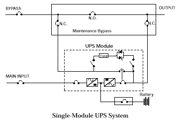
Most power supplied to a data center is conditioned power with stored energy as reserve. Consequently, the UPS requirements are very large in magnitude, ranging into the megawatts. This creates a distribution nightmare, considering that most readily-available single-module UPS are at most rated at 800 kilovolt-amperes (kVA). To develop high capacity output of UPS power, single-module UPS systems are installed in parallel. As many as seven modules may be installed in parallel to increase the capacity of the UPS systems.


Static-Switch Bypass

A large UPS system is typically provided with a static-switch bypass . If the UPS modules fail, the critical load will transfer to this bypass. Some designers also provide a wraparound maintenance bypass to the static switch, so as to isolate the UPS modules and static-switch bypass. However, the maintenance bypass provides unconditioned power to the critical load—with no stored energy reserve as backup.


In the event of a power loss—even for just milliseconds—the batteries associated with UPS modules provide the power to maintain continuity. If there is loss of power to the UPS module, the batteries will continue to provide power until their capacity is depleted and a low-voltage condition occurs. At that time the static bypass will transfer to a secondary source, if available and within voltage tolerances.


The Importance of Grounding

Tier-III installations are typically designed with N+1 modules — the total number of modules necessary to meet the load requirements, plus one additional module for redundancy — and are provided with a static-switch bypass to transfer power in the event of failure of the UPS modules. It is important that, if there is a problem with the UPS modules, the critical load transfers from UPS modules to static-switch bypass. In order for the transfer to occur, a good solid ground must be established.

Typically a ground wire is run, along with phase conductors, from the service substation to static-switch bypass. If the termination is not installed or maintained properly, an impedance may develop between the two reference grounds and cause increased voltage in the circuit phase conductors, pushing the tolerance range within which the bypass will transfer and causing the static switch to fail to transfer, even though a good secondary source is available.

It is vital that the ground is properly connected at the static-bypass cabinet, and zero potential is maintained at the neutral to ground bond at the static bypass and at the double-ended substation. Otherwise, the UPS system could fail to transfer to static bypass.

Most manufacturers recommend that a neutral and ground conductor be run from output isolation transformers from the UPS modules to static-switch bypass, where they will be connected to their respective bus. The neutral and ground should be bonded — in accordance with National Electrical Code (NEC) requirements — because the output of the transformers are separately derived systems. A ground is also run from the neutral and ground bond of double-ended substations to the neutral ground bond at the static switch. Because there is no transformer at the static switch to help establish a separately derived system, an electrically common point is established between the double-ended substation and static-switch bypass. This configuration, however, has the potential for creating problems with load continuity.


A major reason why data centers go off-line is human error. Where there is human intervention, there are potential problems with ground faults. Ground faults can be very difficult to predict and control and can cause havoc in large multi-module UPS systems. Smaller UPS systems — less than 225 kVA — have output isolation transformers with internal static-switch bypass. The output of the static-switch bypass and UPS is routed through a common output isolation transformer. This in turn protects the UPS system from ground faults and transients that may develop at the critical load.

On the other hand, UPS modules in larger systems typically have an output isolation transformer, but the static-switch bypass does not. If a ground fault occurs downstream from the UPS system but upstream from the power distribution unit, the fault will travel back to the source: the double-ended substation. To reach the source and help clear the fault, the load will transfer to the static-switch bypass. This can cause the main circuit breakers at the double-ended substation to trip on ground fault and take the critical load off-line. Because the breakers at the output of the static bypass and at the double-ended substations are approximately the same size, and are significantly larger than the minimum 1,000-amp setting allowed by NEC, it is possible that a facility's entire system will lose power.


Grounded Solutions

There are various solutions currently employed to help mitigate potential problems of ground faults and impedance between the two separately-derived grounds — at the static-switch bypass and the double-ended substation. A transformer can be installed at the input of the static switch so that the neutral-to-ground bond established at the static switch will come from a separate source.

This approach, however, can be costly, and the required transformer can be extremely large. Also, the transformer will contribute to inrush and additional impedance. But it may be of benefit in limiting maximum fault current available downstream from the UPS system.

Another popular solution is to implement high-resistance grounding. HRG is not commonly used on a low-voltage system. The intent is to introduce a resistor to limit the current that flows at the neutral and ground bond, where the ground-fault current transformer monitors fault current.


This method is difficult to implement, because it requires calculation of system capacitance and requires fine-tuning of the resistor in the field. It is also dangerous, requiring highly trained personnel to monitor the ground-fault alarm and then trace through the distribution system and isolate the source of the fault. Human error is already a major source of data center power loss. It does not seem a good idea to introduce yet more human intervention to trace and isolate fault current. In addition, the setting for the ground-fault sensors needs to be revisited any time a significant load is added that may change the system capacitance.

It may seem that the solution is as simple as providing a zone-interlocking relay-protection scheme from the double-ended substation down to UPS static switch, and a distribution switchboard downstream of the UPS system. But ground-fault coordination is very difficult to design and install. Also, the static switch will transfer from the UPS module at a much faster speed than any fast-acting relay.

It is essential to maintain operation of mission-critical facilities and data centers with a reliable distribution scheme. The design engineer should coordinate with the client to establish design parameters based on economics and level of required reliability for mission-critical facilities and ensure that the final product is a facility that meets all of the client's long-term operational requirement.


About the Blogger

Strategic Media Asia (SMA) is one of the approved CPD course providers of the Chartered Institution of Building Services Engineers (CIBSE) UK. The team exits to provide an interactive environment and opportunities for members of ICT industry and facilities' engineers to exchange professional views and experience.

SMA connects IT, Facilities and Design. For the Data Center Consideration Series, please visit 


(1) Site Selection,
(2) Space Planning,
(3) Cooling,
(4) Redundancy,
(5) Fire Suppression,

(6) Meet Me Rooms, and
(7) UPS Selection


Tuesday, August 23, 2016

Data Center Design Consideration: Raised Floor

Despite all many studies claiming raised floor is no longer necessary in data center design, it is still present in the vast majority of data centers or computer rooms. We are going to address several important factors to consider (structural strength, airflow and leakage if you’re using it for cooling and static dissipation) when choosing and installing a raised floor in your critical facilities.


(1) Cooling, Floor Tightness and Airflow


The overhead air ducts in slab (non-raised-floor) designs tends to be limited. When chilled air is delivered under a raised floor and preforming "spot cooled", simply rearranging perforated floor tiles is enough to change the cooling distribution. Also, the plenum under a raised floor offers room for cabling (usually power cables) that doesn’t require the kind of added labor and infrastructure that overhead cabling calls for—cable racks or baskets.


However, massive underfloor air delivery is often problematic and accounts for many of today’s data center cooling problems. Air turbulence can cause uneven air pressure and spotty air delivery. Raised floor heights of 18 inches, 24 inches and even 30 inches or more are needed, and few buildings have the slab-to-slab clearance for that.

On the other hand, the plenum under a raised floor can be subject to obstructions (particularly cabling) and other inefficiencies that hamper cooling. The general consensus is that a raised-floor design cannot meet the cooling needs of higher-density deployments (perhaps in the range of 8–10 kW per rack and up).


There are also code considerations with underfloor air delivery. A data center that uses the raised floor space for cooling may be required by Article 645 of the National Electrical Code to also have an emergency power off button next to exit doors. However, data center owners can avoid this requirement in a number of ways, including not using a raised floor at all.


It’s important that the panels must be square and tight to minimize air leakage, and every edge next to walls and air conditioners and around pipe penetrations must be sealed.

One important thing to remember is that while adjustable dampers on tiles can be very valuable for balancing air delivery among cabinets, adding a damper to any tile effectively reduces its “open percentage” and its airflow, even when the damper is fully open.

For example, a Tate 25% open perforated panel with no damper will pass 746 cfm of air at 0.1 inches of static pressure under the floor. Simply adding a damper and leaving it fully open reduces this to 515 cfm. That’s the equivalent of only 17.4% open. With a 56% open grate tile, the difference is even more dramatic - 2,096 cfm with no damper and only 1,128 cfm with a fully open damper (a reduction from 56% to 30.5% open).

An examination of manufacturers’ airflow characteristics and images, with and without dampers, can quickly reveal this effect.


(2) Ramp


Ramps also take up a lot of space. The Americans with Disabilities Act (ADA) requires at least a 1:12 slope, which means a ramp must have one foot of length for every inch of floor height. In new buildings, a depressed slab will keep the raised floor even with the surrounding corridors, but that takes a special structure.


(3) Building Floor Levelness & Load Capacity


Most building floor slabs are uneven, and they’re designed to flex as weight is added. Raised floors use adjustable pedestals that result in a very level floor surface without needing to level the slab. This makes it easier to align rows of cabinets, as well as to roll equipment into place.

However, the capacity of the floor may become a structural concern if the data center grows faster than originally planned or new, heavier equipment is deployed beyond what the company had intended at construction time. Furthermore, seismic activity poses a danger to raised floors beyond what slabs face.


(4) Evaluation of Raised Floor and Panels


Modern raised floors for data centers are usually made of cement-filled steel or cast aluminum. For easy access, we need “lay-in” panels that can be easily removed, rather than the screw-down type that are bolted to the pedestals at each corner. And because cabinets in today’s data centers are getting heavier, we need the strength and stability of a “bolted stringer” understructure, rather than panels that just self-lock to the pedestals at the corners.

Panels have historically been labeled and marketed for their “concentrated load” ratings. This is the maximum load that can be applied to the weakest one square inch of the tile without deforming it by more than a specified amount. But different manufacturers provide other ratings, including "uniform load" (the average weight per square foot the panel can support when weight is evenly distributed across its four square-foot surface), "yield point" (where the panel permanently deforms) and "ultimate load" (where the concentrated load actually causes the panel to collapse or break).

Either way, it is the concentrated load or design load, not the uniform load, we care about most, since cabinets usually sit on small leveling feet or casters, not solid full-size bases. Uniform load is meaningless in a data center.


So what strength do we really need? There is a tendency to use the highest load rating simply because cabinets are getting heavier, but is that really necessary?

Stronger floors usually weigh more which, depending on the building slab rating, may reduce the useful cabinet weight that a raised floor can support. This is a reason to compare the weights of similarly rated panels, and is also why some data center designers advocate cast aluminum floors despite their much higher cost.

Although some cabinets may weigh 2,500 pounds or more, others will probably weigh less. If you only have several heavy cabinets, extra pedestals under them may be fine, but if you have too many heavy cabinets, extra pedestals could be forgotten with resulting damage to the floor.

Another important rating is "rolling load,” because we need to get cabinets across the floor and into position. One suggestion is to install stronger panels in your delivery paths, so the panels with different strengths are interchangeable in the floor structure.

It is important to carefully read manufacturers' data sheets. Since not all floor manufacturers test and specify the same way, it is also good to know how tests were run to compare ratings and determine whether they were done by independent testing labs.


(5) Raised Floor's Surface Material


We should also be concerned about the anti-static characteristic of a floor material. There are two types of floors that are often confused: conductive and static dissipative. Technical definitions classify static dissipative as a particular type of conductive floor, but manufacturers of raised floor products for data centers and clean rooms will generally identify them separately. Conductive flooring is typically used in clean rooms, where people are handling microchips. This type of flooring has a lower resistance to ground than static dissipative products. Conductive flooring is not needed, nor recommended, for data centers.

In data centers, we need static dissipative floors that will conduct static charges of more than 100 volts away from our bodies and clothing and through the floor tile to the ground. This requires a surface material to have the necessary static dissipative qualities, and a grounded understructure that prevents the generation of static electricity. The understructure should also conduct electrical charges away so that they are not harmful to our equipment. Ratings should be based on the resistance from any point on the panel surface to the pedestal, which also needs to be properly grounded to work.

The surface material on a computer room floor should be a zero-maintenance product. It should never need to be waxed or buffed, as wax accumulates dirt and must be removed with liquids, and buffing creates dust. The material must also be hard enough for equipment to roll over and sit on without denting or deforming. This rules out rubber and vinyl materials. And, of course, carpet of any kind should never be used, as it both creates and traps particulates. The most commonly used surface covering in data centers is known as high-pressure laminate (HPL). It can be made with the necessary static dissipative qualities and also has the hardness and maintenance characteristics needed. It should also be made so the laminate edges are not easily damaged.


(6) Budget, Cleaning and Maintenance


The area under a raised floor is a dirt and debris trap, but cleaning can be problematic. Furthermore, other problems such as addressing (and even identifying) moisture and breaches in walls plague this approach. Also, since out of sight is out of mind, the temptation to leave unused cabling and other junk in the plenum may be irresistible, particularly in a time-pressed environment, thus exacerbating the problem.

For data centers operated more than 5 - 10 years, replacing individual floor panels with special size may be required due to wear out and daily operations. Minimum order quantity (MOQ) requirement specifies the lowest quantity of the raised floor panels that a supplier is willing to sell. Spare panels are usually recommended and prepared in the data center design stage or extra budget may be required to settle the tailor-made issue.


(7) Security


This concern is particularly acute in the co-location facilities that serve multiple customers. For security concern, some cabinets stored sensitive data for critical purposes are installed inside a cage unit (from ceiling to raised floor, from raised floor to concrete slab floor) which is separated from other cabinets in a data hall. It should be prepared for this kind of installation.


* The Performance Selection Chart and Air Flow information are provided by MUFLOOR ASIA COMPANY LIMITED (http://www.mufloor.com). For details, please contact the local distributor.


About the Blogger

Strategic Media Asia (SMA) is one of the approved CPD course providers of the Chartered Institution of Building Services Engineers (CIBSE) UK. The team exits to provide an interactive environment and opportunities for members of ICT industry and facilities' engineers to exchange professional views and experience.

SMA connects IT, Facilities and Design. For the Data Center Consideration Series, please visit 


(1) Site Selection,
(2) Space Planning,
(3) Cooling,
(4) Redundancy,
(5) Fire Suppression,

(6) Meet Me Rooms, and
(7) UPS Selection


Monday, July 18, 2016

Data Center Design Consideration: UPS

Uninterruptible Power Supply (UPS) is one of the key component of a data center. Understanding of the UPS technology is critical and important for the data center design.


Transformer-based or Transformer-free UPS?


There is growing interest in using transformer-free UPS modules in higher power, three-phase, mission-critical power backup applications (e.g., 200 kW to 5 MW). However, many organizations are unclear about which architecture — transformer-based or transformer-free — is best suited for a particular application.


With limited floor space and modular components in data centers, more flexible, smaller footprint UPS units are desirable by companies in the near future. On the one hand, the latest transformer-free systems offer better efficiency, a smaller footprint, and improved flexibility while providing high levels of availability. Driven by data center designer demand, most leading UPS suppliers offer both topologies. On the other hand, transformer-based UPS systems excel at providing the highest capacities and availability while simplifying external and internal voltage management and fault current control.


Currently, large transformer-free systems are constructed using modular building blocks that deliver high power in a lightweight, compact package. This modular design offers advantages when the timing of future load requirements is uncertain by allowing capacity to be more easily added as needed, either physically or via control settings. On the other hand, a modular design means higher component counts, which may result in lower unit mean time between failure (MTBF) and higher unit service rates.


For high-power enterprise data centers and other critical applications, a state-of-the-art transformer-based UPS still provides an edge in availability. Transformers within the UPS provide integrated fault management and galvanic isolation as well as greater compatibility with critical power distribution system requirements that should be considered when designing a high availability UPS system. Technology developments and configuration options allow the latest transformer-based designs to operate at higher efficiencies compared to previous designs, making them more comparable to the transformer-free models in terms of efficiency.


In general, 200 kW is a threshold below which the space, weight, and cost advantages of transformer-free UPS systems outweigh the robustness and higher capacity capabilities of transformer-based systems. The under-200 kW applications can benefit from the high efficiency and excellent input power conditioning through active components offered by transformer-free designs. In addition, the scalability of a modular transformer-free UPS can help avoid over-provisioning while maintaining operational efficiency.


FACTORS TO CONSIDER


Both approaches use a double-conversion process (Figure Above) to provide power protection for mission-critical applications. The primary difference between the two technologies is in their respective use of transformers.

A transformer-based UPS may use a transformer before the rectifier and requires an isolation transformer after the inverter to derive the voltage being delivered to the critical load.

Transformer-free UPS designs use power and control electronics technologies to eliminate the need for an isolation transformer as an integral part of the inverter output section.


TRANSFORMER-BASED UPS DESIGN


Large systems are typically manufactured based on serviceable sub-assemblies and are available in discrete units rated up to 1,100 kVA. Key components of this design include:


  • A passive filter (inductors and capacitors) on the rectifier input to reduce input current distortion and improve the power factor.
  • A six-pulse (or optional twelve-pulse), semiconductor (SCR)-based rectifier on the input. Optionally, an additional transformer (Xfmr) provides AC-DC isolation for the DC bus and the battery.
  • A DC energy storage system (typically a battery) connected directly to the DC bus between the rectifier and the inverter to provide AC output power ride-thru capability during a loss of AC input power. This example uses 540 VDC.
  • An insulated gate bipolar transistor- (IGBT) based, pulse-width modulation (PWM) inverter on the output.
  • An isolation Xfmr on the inverter output to derive the appropriate output voltage. This also provides a convenient and solid point for referencing the AC output neutral to ground. This neutral ground connection provides excellent common mode noise rejection.
  • A passive filter on the inverter output to provide a very low distortion AC voltage supply.
  • An automatic bypass switch (static switch) using power SCRs provides instantaneous switchover to an alternate source if a UPS output disturbance occurs.


TRANSFORMER-FREE UPS DESIGN


Transformer-free UPS topologies replace simple passive magnetic-voltage transformation functions with solid-state power electronics circuitry. Figure above shows a simplified block diagram of a transformer-free UPS design. There are a number of key differences listed below between this circuit and the unit depicted in the figure.


  • By replacing passive power components (transformers, capacitors, inductors) with power circuit assemblies utilizing PWM power conversion techniques, transformer-free UPS rectifiers are physically smaller and produce low input current harmonics with near unity input power factor.
  • Typically, the UPS battery in transformer-free applications is connected to the internal DC bus (about 800 VDC in the previous example) through an integrated bi-directional DC-DC converter. This puts an additional power conversion element in series with the battery.
  • Using similar PWM power conversion techniques, transformer-free UPS inverters are physically smaller as well, and produce low output voltage harmonics over a wider range of connected load characteristics.
  • The bypass function (static bypass switch) is similar to the transformer-based design. However, without external transformers added, the bypass AC input must be the same voltage as the inverter AC output.
  • Transformer-free UPS are typically designed and styled for both computer room in-row lineups and equipment room installations. Complete transformer-free UPS units are typically an assembly of standard frames plus functional control and power modules.

  • A transformer-free UPS is lighter and smaller than the power-equivalent transformer-based design with both physical volume and footprint being less. And, according to the fall 2012 Data Center Users Group (DCUG) survey, data center energy costs and equipment efficiency are the top-of-mind issue for DCUG members, with nearly half of the respondents listing it as one of their top facility/network concerns.


However, other external transformers may be required for AC-DC isolation purposes, safety reasons, AC voltage changes, or to provide power distribution flexibility. With the addition of external transformers, the overall facility weight and footprint totals may be higher than with a transformer-based UPS design with implications for end-to-end system efficiency. If transformers need to be added to a transformer-free unit to make it compatible with a facility, a transformer-based unit may be a better solution.

Transformer-free UPS topologies have emerged to meet the demand for more efficient, flexible, smaller footprint, lighter weight UPS systems. The price of these performance feature improvements has been the replacement of a few robust but physically large, passive components, such as transformers, inductors, and capacitors with functional power electronic equivalents packaged in field replaceable, modular sub-assemblies. It is reasonable to expect that the transformer-free units will have service call rates somewhat higher than their transformer-based counterparts.


TECHNICAL FEATURES AND PERFORMANCE DIFFERENCES


In choosing between transformer-based and transformer-free UPS solutions, a system designer should determine where transformers are best utilized and whether they should be internal and/or external to the UPS in view of physical and electrical distribution requirements and tradeoffs. It’s important to review the techniques and tradeoffs utilized in the various rectifier, DC energy storage, inverter, and static bypass functions of these two UPS designs for various UPS system performance functions including:


• Site planning and adaptability to change

• Reliability and availability

• Robustness

• DC energy storage system isolation

• Engine-generator interface

• UPS output interface considerations

• High resistance grounding

• Fault current management

• Arc flash energy

• Isolation

• Maintainability

• External components needed to complete the system design

• Total cost of ownership

• Capital expenses (CAPEX) and operating expenses (OPEX)


When considering the total cost of ownership for these two architectures, it is important to include both the initial upfront or CAPEX as well as the ongoing or OPEX to power, maintain and service various options.


Technological evolution is constantly impacting the relative efficiency of transformer-based and transformer-free solutions. After years of optimizing performance, transformer-based UPS systems have achieved a relatively flat efficiency curve from 30% to 80% loading where typical tier 3 and tier 4 data centers operate. The latest transformer-free designs also have very flat curves down to as low as 20% of capacity, and have efficiencies in the 95% to 96% range in double-conversion mode. A study of the whole system design is necessary to determine the relative efficiencies as the addition of transformers, and the efficiency of those transformers, will have an impact.


In summary, transformers, whether internal or external to the UPS, are necessary to establish circuit isolation and local neutral and grounding points, as well as to provide voltage transformation points. This facilitates, for example, the implementation of very high power density installations based on 600V distribution sources, subsequently stepped down to 208/120V for IT load applications. When transformers are utilized in conjunction with the UPS internal DC link, DC-to-AC output, and AC-to-DC input isolation can be provided, reducing or eliminating the risk of DC faults propagating upstream or downstream of the UPS.


About the Blogger

Strategic Media Asia (SMA) is one of the approved CPD course providers of the Chartered Institution of Building Services Engineers (CIBSE) UK. The team exits provide an interactive environment and opportunities for members of ICT industry and facilities' engineers to exchange professional views and experience.

SMA connects IT, Facilities and Design. For the Data Center Consideration Series, please visit 


(1) Site Selection,
(2) Space Planning,
(3) Cooling,
(4) Redundancy,
(5) Fire Suppression, and

(6) Meet Me Rooms


Monday, May 30, 2016

Thank you for coming to the Data Center Technical Visit in May 2016

A Big Thank You to all visitors, who join the data center technical visit, and the coordination granted by the data center team in Tseung Kwan O, Hong Kong!

The half-day visit on 20 May 2016 enables us to create an interactive environment for members of IDC industry and infrastructure engineers and to exchange professional views and experience on mission critical facilities (cooling system, electrical system, fire suppression system, NOC, carrier-neutral meet-me rooms (MMR), etc.) and data center services.


We look forward to cooperating with the industry and organizing the similar event in the near future!


About the Organizer

Strategic Media Asia (SMA) is one of the approved CPD course providers of the Chartered Institution of Building Services Engineers (CIBSE) UK.

The team exits provide an interactive environment and opportunities for members of ICT industry and facilities' engineers to exchange professional views and experience.

SMA connects IT, Facilities and Design. For accreditation details and background, please visit www.stmedia-asia.com/about.html.

Friday, May 20, 2016

Keep Your Knowledge Current in Electrical Design for Mission Critical Supply

Within the built environment, mission critical facilities and data centers have particular power requirements that significantly impact how they are designed and operated. Further to the


(1) Site Selection,
(2) Space Planning,
(3) Cooling,
(4) Redundancy and
(5) Fire Suppression,


you are recommended to join the 2-day advanced learning (CIBSE approved CPD Course) in Electrical Design for Mission Critical Supply.


With more than 18 years experience in critical facilities and electrical system design, the Instructors (with Chartered Engineer (CEng) status) will detail about the international standards, best practices and design project experience. You will gain insight into the critical supply system, from power components to distributions and efficiency; from power requirements to sizing, design, testing and commissioning.


-- Concept on primary supply and secondary supply
-- Power flow in mission critical supply system
-- Features of major equipment for critical supply

  > Uninterrupted power supply and power storage
  > Backup generator
  > Automatic transfer switch
  > Static transfer switch
  > Isolation transformer

-- Efficiency assessment
-- Power quality review
-- Configuration diagram of critical supply (N+1 / 2N) design & analysis
-- Review of cable sizing to incorporate harmonics content
-- Earthing system design
-- Testing and commissioning requirements
-- Brief of Systems Merging Appraisal Test (SMAT)


This is an advanced learning section on top of the Data Center Facilities Design & Infrastructure Engineering. For details, please refer to http://www.stmedia-asia.com/newsletter_6.html.


About the Organizer

Strategic Media Asia (SMA) is one of the approved CPD course providers of the Chartered Institution of Building Services Engineers (CIBSE) UK.

The team exits provide an interactive environment and opportunities for members of ICT industry and facilities' engineers to exchange professional views and experience.

SMA connects IT, Facilities and Design. For accreditation details and background, please visit www.stmedia-asia.com/about.html.


Tuesday, April 26, 2016

Get Ready to Become a Registered Communications Distribution Designer (RCDD)

We are pleased to announced the RCDD Credential Program (DD102: Designing Telecommunications Distribution Systems) for Structured Cabling System Design was fully completed last week during 18 - 22 April 2016. The team sincerely thank you for all participants and the coordination granted by the overseas training partner and the US BICSI, which enables us to successfully launch the credential program first time in Hong Kong / South China.


We look forward to the participants achieving the RCDD qualification and getting certified soon.

For the details of RCDD credential program, please visit www.stmedia-asia.com/rcdd.html.


About the Organizer


Strategic Media Asia Ltd (SMA) is one of the Approved CPD Course Providers of the Chartered Institution of Building Services Engineers (CIBSE). SMA exists to provide an interactive environment and opportunities for members of IDC industry and engineers to exchange professional views and experience on data center design, critical infrastructure system, electrical and mechanical facilities, etc.

SMA connects IT, Facilities and Design. For details, please visit our website at www.stmedia-asia.com/trainings.html.


Tuesday, April 5, 2016

Facilitation Measures for Data Center Development Extended in Hong Kong

The Hong Kong Government announced that the Chief Executive in Council (CE in Council) has approved the extension of the existing concessionary scheme to encourage the development of data centers by conversion of old existing industrial buildings and lease modification of industrial lots.


"The Government is committed to promoting the development of data centers in Hong Kong to meet industry demand, which is expected to rise further in the next few years due to the increasing use of cloud computing and other new initiatives such as smart city development and big data applications," a spokesman for the Innovation and Technology Bureau said.


"Given the competing demands for new government sites, conversion of old industrial buildings would be a viable option for data center operators. With recent technology advancements in modular data centers, more industrial buildings can become suitable for such use."


The existing time-limited concessionary scheme for data centers was introduced in 2012. With the CE in Council's approval, the following measures will continue after March 31, 2016 in Hong Kong:


(1) to exempt the waiver fees for issuing waivers for applications approved by the Lands Department (LandsD) for change of use in parts of industrial buildings aged 15 years or above in "Industrial", or "Other Specified Uses" annotated "Business" or "Commercial", zones to data centers of all tiers for the lifetime of the existing building or until expiry or determination of the current lease of the lot concerned, whichever is the earlier;


(2) to accept applications for lease modification (including land exchange) tailor-made for development of high-tier data centers wholly or in conjunction with other uses on existing industrial lots, instead of requiring a lease modification up to the optimal uses and maximum development intensity that could possibly be allowed for the site; and


(3) to continue the arrangement that Conditions of Sale for new sites identified for data center development be tailor-made for high-tier data center use with specified gross floor area, including the two remaining dedicated sites in Tseung Kwan O.


The concessionary scheme has attracted a positive market response, with a total of 27 applications received up to March 29, 2016, for converting parts of existing industrial buildings to data center use under the first measure above.


In addition, the LandsD together with the Office of the Government Chief Information Officer (OGCIO) will streamline the procedures for issuing waivers for change of use of industrial buildings under the first measure mentioned above, aiming to approve new applications within a much shortened time frame of around two weeks. For details, please visit websites of the LandsD (www.landsd.gov.hk) and the OGCIO (www.datacentre.gov.hk).


In 2012, the Government reserved 3 dedicated sites in Tseung Kwan O for high-tier data center development, of which one was sold in October 2013. It is expected that the Government will put to sale the other two sites within the coming few years.


Source: www.info.gov.hk


About the Blogger


Strategic Media Asia Ltd (SMA) is one of the Approved CPD Course Providers of the Chartered Institution of Building Services Engineers (CIBSE). SMA exists to provide an interactive environment and opportunities for members of IDC industry and engineers to exchange professional views and experience on data center design, critical infrastructure system, electrical and mechanical facilities, etc.

SMA connects IT, Facilities and Design. For details, please visit our website at http://www.stmedia-asia.com/trainings.html.


Wednesday, March 30, 2016

Four Monitoring Capabilities for Data Center Power Systems

The primary method that people use to measure the energy effectiveness of their data centers is power usage effectiveness (PUE). PUE compares the power used for computing capacity and the overall power used by the data center (PUE = Total Facility Power / IT Equipment Power). The inverse of PUE is data center efficiency, according to The Green Grid association.


Currently, the industry average PUE is reported to be around 2.0, but a number of new and proven data center infrastructure technologies are available to advance efficiency and reduce PUE to 1.5 or lower without compromising availability. There are 4 key actions data center managers can take with integrating monitoring capabilities into power systems that can help improve efficiency and advance PUE.


Monitoring Power Usage


With power densities and energy costs rising, the ability to monitor energy consumption is essential for advancing PUE. Where power is measured can have an effect on how efficiency is measured.

For a comprehensive picture of data center power consumption, power should be monitored at the UPS, the room power distribution unit (PDU), and within the rack. These data points should be consolidated and reported within an enterprise data center infrastructure management (DCIM) tool that can be shared by both facilities and IT management. DCIM tools (if specified early and fully integrated) can provide an overarching view of the data center, which will provide insights into how effectively or ineffectively the computing power of the data center is being used.


Specifically, measurements taken at the UPS provide a base measurement of data center energy consumption that can be used to calculate PUE and identify energy consumption trends. Monitoring the room PDU prevents overload conditions at the PDU and helps ensure power is distributed evenly across the facility.


The best view of IT power consumption comes from intelligent PDUs inside racks, which feature integrated monitoring and control capabilities to enable continuous power monitoring and feedback to the DCIM tool. Because rack power consumption varies based on equipment within the rack and its load, each rack should be equipped with a PDU—two for dual bus environments—capable of monitoring power consumption to the rack PDU, as well as overload-protected receptacle groups and, where required, at the receptacle level.


These systems can provide PDU, branch-level, and receptacle-level monitoring of voltage, kW, current, and kWh, giving the most direct measurement of power consumption and supporting higher data center efficiency and availability.


Monitoring Rack Conditions


With increasing densities, a single rack can now support the same computing capacity that used to require an entire room. Visibility into conditions in racks can help prevent many of the most common threats to rack-based equipment, such as accidental or malicious tampering.


If specified and installed correctly, rack monitoring units can be configured to trigger alarms when rack doors are opened, water or smoke is detected, or temperature or humidity thresholds are exceeded. Many units are equipped with cameras to capture video of the event. These “eyes inside the rack” can be connected to central monitoring systems where environmental data can be integrated with power data from rack PDUs, while providing local notification by activating a beacon or other alarm if problems are detected.


Monitoring Energy Efficiency


Automating collection and analysis of data from power systems can help reduce energy consumption while increasing IT productivity. Energy efficiency monitoring can track total data center consumption, automatically calculate and analyze PUE, and optimize the use of alternative energy sources.


Using real-time data from the many support systems, the monitoring system can track and trend total infrastructure power use and compare this to capacities. For example, for UPS power output, determine when UPS units are running at peak efficiency, and report Level 1 (basic) PUE. Monitoring at the room or row PDU provides the ability to more efficiently load power supplies, dynamically manage cooling, and automatically calculate Level 2 (intermediate) PUE. Panel board monitoring provides visibility into power consumption by non-IT systems, including lighting and generators, to ensure efficient use of those systems.


Finally, rack-level monitoring provides the most accurate picture of IT equipment power consumption and can support Level 3 (advanced) PUE reporting. The ability to automate data collection, and consolidate and analyze data related to efficiency—which is one of the primary jobs of the DCIM tool—is essential to data center optimization. These functions free up data center staff to focus on strategic IT issues.


Monitoring Batteries


Batteries have long been known as a weak link in the power chain. To prevent data loss and increase uptime, most data centers specify and require a dedicated battery monitoring system, which should be installed when the data center goes online. Using a predictive battery monitoring method can provide early notification of potential battery failure. The best practice is to implement a monitoring system that connects to and tracks the health of each battery within a string.


The most effective systems continuously track all battery parameters, including internal resistance, using a dc test current to ensure measurement accuracy and repeatability. Supported by a well-defined process for preventive maintenance and replacement, monitoring batteries can significantly reduce the risk of dropped loads due to battery failure, optimize battery life, and improve safety. The use of a battery monitoring system has an excellent payback period but, more importantly, provides peace of mind to the data center operator that the power system will react and support a load during a power outage.


INTELLIGENT CONTROLS


Previous generations of infrastructure systems were unable to adjust to dynamic load variations. UPS systems, meanwhile, operated most efficiently at full load, but full-load operation is the exception rather than the norm. The lack of flexibility in power systems led to inherent energy inefficiency.


Integrating intelligent control capabilities into data center power systems can help minimize the amount of energy being lost by enabling data center managers to tailor the performance of the UPS system to the specific efficiency and availability requirements of the site. When proper application of these capabilities is followed, it can enable double-conversion on-line UPS systems to operate at efficiency levels up to 97% while the inverter remains in operation.


Advanced UPS systems can employ an energy optimization mode that powers the load in reverse-transfer mode while keeping the UPS inverter at the ready to pick up the load in the event of a utility disturbance. An even higher degree of energy optimization provides power conditioning as well. The result is increased efficiency without compromising availability.


It is important that data center managers do not compromise on distribution and server power supply performance. Attention to distribution transformer and server power supply efficiencies can also reap huge benefits in improving PUE. Deploying TP1-rated distribution transformers can improve partial load efficiency by as much as 0.5%. High-efficiency server power supplies, while initially more expensive, can pay for themselves over their useful life.


About the Blogger


Strategic Media Asia Ltd (SMA) is one of the Approved CPD Course Providers of the Chartered Institution of Building Services Engineers (CIBSE). SMA exists to provide an interactive environment and opportunities for members of IDC industry and engineers to exchange professional views and experience on data center design, critical infrastructure system, electrical and mechanical facilities, etc.

SMA connects IT, Facilities and Design. For details, please visit our website at http://www.stmedia-asia.com/trainings.html.


Tuesday, February 2, 2016

Data Centers and "One Belt, One Road"

With the aim to connect major Eurasian economies through infrastructure, trade and investment, President Xi Jinping launches the 13th 5-year plan and “One Belt, One Road” strategy which promote two international trade connections: The land-based "Silk Road Economic Belt" and oceangoing "Maritime Silk Road."


Source: globalconnections.hsbc.com


The “Belt” is a network of overland road and rail, oil and natural gas pipelines, and other infrastructure projects that run along the major Eurasian Land Bridges, through China-Mongolia-Russia, China-Central and West Asia, China-Indochina Peninsula, China-Pakistan, Bangladesh-China-India-Myanmar.


The “Road” is a network of planned ports and other coastal infrastructure projects from South and Southeast Asia to East Africa and the northern Mediterranean Sea.


Source: greendatacenternews.org


Data Centers, the mission critical purpose-built facilities, take important role in the “One Belt, One Road” strategy. It serve users for telecoms, electronics and the Internet industries first, followed by companies that develop the Internet of Things, aiming to foster a hi-tech information industry cluster and to accelerate the enterprises' digital transformation such as mobility, cloud and big data.


Not only are they the essential infrastructure supporting various industries such as oil and gas, trading and finance, but also the catalyst for the development of new industries and applications that empower the economic growth.


China Mobile, for example, is building the largest data center in Northwest China. Located at the Karamay Cloud Computing Industrial Park, the mission critical facilities offer 119,000 sqm of floor space and capable of hosting 14,000 racks. The facilities in phase one, by the end of 2016, will offer 3,600 racks and start to provide the services.


Source: atkinsglobal.com


The data center not only boasts a strategic geographic position as it is located on the Eurasia Land Bridge, which is the rail transport route for moving freight and passengers overland from Pacific seaports in the Russian Far East and China to seaports in Europe, but also becomes a symbolic meaning taken by one of the key telecommunications players in the world and participate in the “One Belt, One Road” strategy.


Countries, investors and enterprises in engineering, critical facilities design, project consultant, construction, operations and management, etc., can take this opportunity to have their staff well trained, to offer quality services, required skills and management systems and to become one of the key infrastructure enablers during years.


About the Blogger


Strategic Media Asia Ltd (SMA) is one of the Approved CPD Course Providers of the Chartered Institution of Building Services Engineers (CIBSE). SMA exists to provide an interactive environment and opportunities for members of IDC industry and engineers to exchange professional views and experience on data center design, critical infrastructure system, electrical and mechanical facilities, etc.

SMA connects IT, Facilities and Design. For details, please visit our website at http://www.stmedia-asia.com/trainings.html.


Wednesday, January 6, 2016

Gain Qualification for Structured Cabling System Design - Become a Registered Communications Distribution Designer (RCDD)


Gain Qualification for Structured Cabling System Design in Hong Kong -
Become a Registered Communications Distribution Designer (RCDD)


Established and approved by the US Building Industry Consulting Services International (BICSI) since 1984, the RCDD credential program is a 5-day professional training (DD102: Designing Telecommunications Distribution System) which details about telecommunications spaces and horizontal and backbone distribution systems design:


- Codes, Standards and Regulations
- Principles of Transmission
- Electromagnetic Compatibility
- Telecommunications Spaces
- Work Areas
- Horizontal Distribution Systems
- Backbone Distribution Systems
- Bonding and Grounding (Earthing)
- Firestopping
- Telecommunications Administration
- Design and Construction
- Project Management
- Networking Fundamentals
- VoIP and Wireless
- Outside Plant (OSP)
- Campus Cabling


Key Content


DESIGN BASICS - Recommended design sequence, cabling infrastructure layout, terms & definitions, overview of standards & codes.


DESIGNING TELECOMMUNICATIONS ROOMS - Determining type number & size according to usable floor space, specifying power, lighting & floor loadings.


DESIGNING HORIZONTAL DISTRIBUTION SYSTEMS - Pathway sizing & routing considerations. Design rules for under-floor duct, cellular floors, conduit, & access floors. Use of ceiling distribution including ceiling zones method. Application exercises; design of under-floor conduit system & comparison with overhead plenum rated method. Specifying copper & fibre optic cabling complete with documentation methods. Examples of cable management during installation & cross connection. Installation sequence for zoned systems.


DESIGNING BACKBONE SYSTEMS - Backbone design & planning, media selection options (copper versus fibre), colour codes, backbone pathways & spaces, sleeves, slots & conduits, planning & designing cable pull boxes, fire stopping, campus backbone design.


DESIGNING EQUIPMENT ROOMS - Electrical power requirements & distribution, environmental, space & structural requirements, electrical ground & bonding. Application exercise: equipment room sizing & location.


DESIGNING ENTRANCE ROOMS - Calculating total space requirements, types of terminations & hardware, electrical protection, network demarcation. Application exercise: entrance facility case study.


RCDDs demonstrate knowledge in design, integration and implementation of information & communications technology (ICT) and related infrastructure components. All sections will be conducted by an instructor who are RCDD certified and have more than 15 years experience in lecturing plus cabling system design.


You are cordially invited to achieve the qualification with more than 5 years ICT / critical infrastructure design experience; OR at least 2 years of verifiable ICT design experience plus 3 years of additional ICT equivalents chosen from combinations of experience, approved education and approved ICT license/certification by BICSI.


Date: 18 - 22 April 2016 (5-day, Monday - Friday)
Venue: 19/F, 93 - 103 Wing Lok Street, Hong Kong (Exit A2, Sheung Wan MTR Station)

5 Days Program Fee: Special rate for early bird enrolment, please refer to www.stmedia-asia.com/rcdd.html. (Including course materials and a digital copy of Telecommunications Distribution Methods Manual (TDMM), 13th edition)


Completion Certificate


After 5-day training (DD102: Designing Telecommunications Distribution System) and passing the online test* in the last day of training, a completion certificate will be granted by the BICSI Authorized Design Training Provider.

* A personal laptop is recommended for the online test.


Achieving RCDD Qualification *


BICSI recommends 125+ hours of self-study (over a period of 5-weeks) following the formal 5-day training (DD102). Examination Format: 2.5 hours, 100 questions, closed-book, multiple choice (knowledge- and application-based questions, minimum 70% correct to pass). The exam (apply through BICSI) can be scheduled at www.pearsonvue.com/BICSI (with an assigned candidate number and scheduling information).

* BICSI Membership, Exam Application and Scheduling Fees are not included in the 5-day program mentioned above.


Enrollment & Registration


Please complete and return an Application Form together with a crossed cheque made payable to “Strategic Media Asia Limited” - Room 403, 4th Floor, Dominion Centre, 43 - 59 Queen's Road East, Hong Kong.

For the RCDD program details, please visit www.stmedia-asia.com/rcdd.html.


About the Organizer


Strategic Media Asia Ltd (SMA) is one of the Approved CPD Course Providers of the Chartered Institution of Building Services Engineers (CIBSE). SMA exists to provide an interactive environment and opportunities for members of IDC industry and engineers to exchange professional views and experience on data center design, critical infrastructure system, electrical and mechanical facilities, etc.

SMA connects IT, Facilities and Design. For details, please visit our website at http://www.stmedia-asia.com/trainings.html.